Picking up from Rounded Cube 3, this chapter focuses on one thing: creating a custom shader.
At this point we can already tell the cube’s faces apart, but we still do not have texture coordinates. Suppose we want a grid pattern stretched across the whole cube so that each individual quad is visible.

Instead of storing UV coordinates directly in the mesh, we can let a custom shader figure out how the texture should be applied. Here is a freshly created surface shader:
<table> <thead> <tr> <th>1 2 3 4 5 6 7 8 9 10 11 12 13 14 15 16 17 18 19 20 21 22 23 24 25 26 27 28 29 30 31 32 33 34 35 36</th>
<th>Shader "Custom/Rounded Cube Grid" { Properties { _Color ("Color", Color) = (1,1,1,1) _MainTex ("Albedo (RGB)", 2D) = "white" {} _Glossiness ("Smoothness", Range(0,1)) = 0.5 _Metallic ("Metallic", Range(0,1)) = 0.0 } SubShader { Tags { "RenderType"="Opaque" } LOD 200 CGPROGRAM #pragma surface surf Standard fullforwardshadows #pragma target 3.0 sampler2D _MainTex; struct Input { float2 uv_MainTex; }; half _Glossiness; half _Metallic; fixed4 _Color; void surf (Input IN, inout SurfaceOutputStandard o) { fixed4 c = tex2D(_MainTex, IN.uv_MainTex) * _Color; o.Albedo = c.rgb; o.Metallic = _Metallic; o.Smoothness = _Glossiness; o.Alpha = c.a; } ENDCG } FallBack "Diffuse" }</th>
</tr>
</thead>
<tbody>
<tr>
<td></td>
<td></td>
</tr>
</tbody>
</table>
This is the default surface shader setup. The important part is the Input struct, which asks for the main texture’s coordinates. Those coordinates are used inside surf, which runs once for every rendered fragment. Since we do not actually have such coordinates, uv_MainTex has to be replaced with something else.
1 2 3 4 5 6 7 8 9 10 11 12 13 14</th>
<th>struct Input { float2 cubeUV; }; … void surf (Input IN, inout SurfaceOutputStandard o) { fixed4 c = tex2D(_MainTex, IN.cubeUV) * _Color; o.Albedo = c.rgb; o.Metallic = _Metallic; o.Smoothness = _Glossiness; o.Alpha = c.a; } }</th>
</tr>
</thead>
<tbody>
<tr>
<td></td>
<td></td>
</tr>
</tbody>
</table>
Because UV data is defined per vertex, we also need a function that runs on each vertex.
<table> <thead> <tr> <th>1 2 3 4 5 6 7 8 9 10 11 12 13 14 15 16 17 18 19 20 21 22 23 24 25 26</th>
<th>CGPROGRAM #pragma surface surf Standard fullforwardshadows vertex:vert #pragma target 3.0 sampler2D _MainTex; struct Input { float2 cubeUV; }; half _Glossiness; half _Metallic; fixed4 _Color; void vert (inout appdata_full v, out Input o) { UNITY_INITIALIZE_OUTPUT(Input, o); } void surf (Input IN, inout SurfaceOutputStandard o) { fixed4 c = tex2D(_MainTex, IN.cubeUV) * _Color; o.Albedo = c.rgb; o.Metallic = _Metallic; o.Smoothness = _Glossiness; o.Alpha = c.a; } ENDCG</th>
</tr>
</thead>
<tbody>
<tr>
<td></td>
<td></td>
</tr>
</tbody>
</table>
To check whether the shader works, we can simply use the vertex position’s XY coordinates as the UVs.
<table> <thead> <tr> <th>1 2 3 4</th>
<th>void vert (inout appdata_full v, out Input o) { UNITY_INITIALIZE_OUTPUT(Input, o); o.cubeUV = v.vertex.xy; }</th>
</tr>
</thead>
<tbody>
<tr>
<td></td>
<td></td>
</tr>
</tbody>
</table>
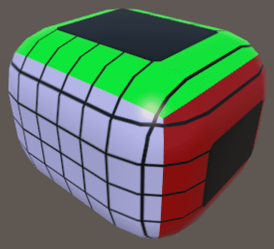
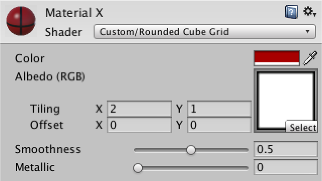
That looks reasonable for the Z faces, but the others turn into a mess. We need different vertex coordinates for them. One option is to support this through a keyword enum shader property.
<table> <thead> <tr> <th>The key point here is that keyword enums decide which face gets rendered, and underneath that behavior sits a corresponding macro definition.
1 2 3 4 5 6 7</th>
<th>Properties { _Color ("Color", Color) = (1,1,1,1) _MainTex ("Albedo (RGB)", 2D) = "white" {} _Glossiness ("Smoothness", Range(0,1)) = 0.5 _Metallic ("Metallic", Range(0,1)) = 0.0 [KeywordEnum(X, Y, Z)] _Faces ("Faces", Float) = 0 }</th>
</tr>
</thead>
<tbody>
<tr>
<td></td>
<td></td>
</tr>
</tbody>
</table>
By defining keywords, we can write different code for each option.
<table> <thead> <tr> <th>1 2 3 4 5 6 7 8 9 10</th>
<th>void vert (inout appdata_full v, out Input o) { UNITY_INITIALIZE_OUTPUT(Input, o); #if defined(_FACES_X) o.cubeUV = v.vertex.yz; #elif defined(_FACES_Y) o.cubeUV = v.vertex.xz; #elif defined(_FACES_Z) o.cubeUV = v.vertex.xy; #endif }</th>
</tr>
</thead>
<tbody>
<tr>
<td></td>
<td></td>
</tr>
</tbody>
</table>
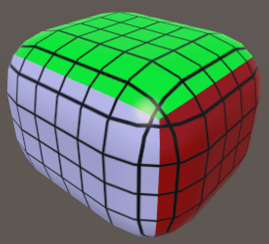
At first glance this looks better, but the grid lines do not line up with the actual quads. Worse, when world-space vertex positions are used, moving or rotating the cube produces odd results.
Before rounding is applied, we need the vertex positions of the original cube. If we can store them in the mesh, we can pass them to the shader. Since vertex colors are not being used for anything else, that channel can carry the data for us.
<table> <thead> <tr> <th>1 2 3 4 5 6 7 8 9 10 11 12 13 14 15 16 17 18 19 20 21 22 23 24 25 26 27 28</th>
<th>private Color32[] cubeUV; private void CreateVertices () { int cornerVertices = 8; int edgeVertices = (xSize + ySize + zSize - 3) * 4; int faceVertices = ( (xSize - 1) * (ySize - 1) + (xSize - 1) * (zSize - 1) + (ySize - 1) * (zSize - 1)) * 2; vertices = new Vector3[cornerVertices + edgeVertices + faceVertices]; normals = new Vector3[vertices.Length]; cubeUV = new Color32[vertices.Length]; … mesh.vertices = vertices; mesh.normals = normals; mesh.colors32 = cubeUV; } private void SetVertex (int i, int x, int y, int z) { … normals[i] = (vertices[i] - inner).normalized; vertices[i] = inner + normals[i] * roundness; cubeUV[i] = new Color32((byte)x, (byte)y, (byte)z, 0); }</th>
</tr>
</thead>
<tbody>
<tr>
<td></td>
<td></td>
</tr>
</tbody>
</table>
Here we have to use Color32 rather than the usual Color type, because vertex color components are stored as single bytes. The full color takes four bytes, which is the same size as a single floating-point value.
If we used normal Color, Unity would convert the 0–1 float range into 0–255 bytes and clip everything outside that range. By converting directly to bytes, we can handle cubes up to 255 units in size, which is more than enough here.
On the shader side, we can now read the vertex color instead of the vertex position. Since the shader interprets vertex color channels as values in the 0–1 range, we need to undo that conversion by multiplying by 255.
<table> <thead> <tr> <th>1 2 3 4 5 6 7 8 9 10</th>
<th>void vert (inout appdata_full v, out Input o) { UNITY_INITIALIZE_OUTPUT(Input, o); #if defined(_FACES_X) o.cubeUV = v.color.yz * 255; #elif defined(_FACES_Y) o.cubeUV = v.color.xz * 255; #elif defined(_FACES_Z) o.cubeUV = v.color.xy * 255; #endif }</th>
</tr>
</thead>
<tbody>
<tr>
<td></td>
<td></td>
</tr>
</tbody>
</table>
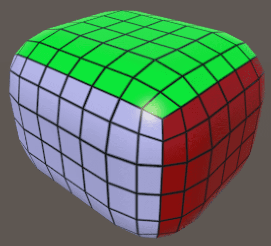
At last, the grid texture works properly. One thing to notice is that the UV coordinates for each pair of faces are mirrored, but that does not matter here because the texture itself is symmetrical.