VLANs provide Layer 2 isolation, so devices in different VLANs cannot communicate directly. To enable communication between them, the network needs Layer 3 routing. In Huawei eNSP, two common designs are available:
- Router-on-a-stick: a router works with a Layer 2 switch. It is inexpensive and suitable for beginners or small lab topologies.
- VLANIF on a Layer 3 switch: the switch performs the routing itself. This is the more common enterprise design and generally offers better forwarding performance.
Option 1: Router-on-a-Stick
In this topology, the switch assigns end devices to separate VLANs and sends tagged traffic to the router through a trunk link. The router then uses subinterfaces to act as the gateway for each VLAN.
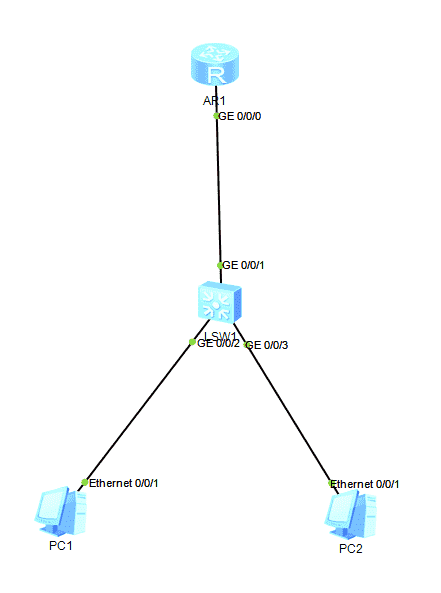
Configure the Layer 2 switch
The first step is to create VLAN 10 and VLAN 20 on LSW1. The ports connected to the PCs use access mode, while the uplink to the router uses trunk mode and permits both VLANs.
<Huawei>system-view # 进入系统视图
[Huawei]sysname LSW1 # 改名交换机
# 批量创建VLAN10、VLAN20
[LSW1]vlan batch 10 20

# 1. 连接PC1的端口G0/0/1:接入VLAN10
[LSW1]interface GigabitEthernet 0/0/1
[LSW1-GigabitEthernet0/0/1]port link-type access
[LSW1-GigabitEthernet0/0/1]port default vlan 10
[LSW1-GigabitEthernet0/0/1]quit

# 2. 连接PC2的端口G0/0/2:接入VLAN20
[LSW1]interface GigabitEthernet 0/0/2
[LSW1-GigabitEthernet0/0/2]port link-type access
[LSW1-GigabitEthernet0/0/2]port default vlan 20
[LSW1-GigabitEthernet0/0/2]quit

# 3. 连接路由器的端口G0/0/0:配置Trunk(允许带VLAN标签通行)
[LSW1]interface GigabitEthernet 0/0/0
[LSW1-GigabitEthernet0/0/0]port link-type trunk
[LSW1-GigabitEthernet0/0/0]port trunk allow-pass vlan 10 20
[LSW1-GigabitEthernet0/0/0]quit
Configure the router subinterfaces
AR1 uses one physical interface with two subinterfaces. Each subinterface terminates the 802.1Q tag for its VLAN and provides the default gateway for that VLAN. The arp broadcast enable command is essential in this eNSP configuration; without it, communication may fail even when the addresses and VLAN IDs appear to be correct.
<Huawei>system-view
[Huawei]sysname AR1

# 子接口0/0/0.10 对应VLAN10
[AR1]interface GigabitEthernet 0/0/0.10
[AR1-GigabitEthernet0/0/0.10]dot1q termination vid 10    # 封装802.1Q,识别VLAN10标签
[AR1-GigabitEthernet0/0/0.10]ip address 192.168.10.254 24  # VLAN10网关
[AR1-GigabitEthernet0/0/0.10]arp broadcast enable           # 关键!开启ARP广播,不通大概率忘这条
[AR1-GigabitEthernet0/0/0.10]quit

# 子接口0/0/0.20 对应VLAN20
[AR1]interface GigabitEthernet 0/0/0.20
[AR1-GigabitEthernet0/0/0.20]dot1q termination vid 20
[AR1-GigabitEthernet0/0/0.20]ip address 192.168.20.254 24
[AR1-GigabitEthernet0/0/0.20]arp broadcast enable
[AR1-GigabitEthernet0/0/0.20]quit
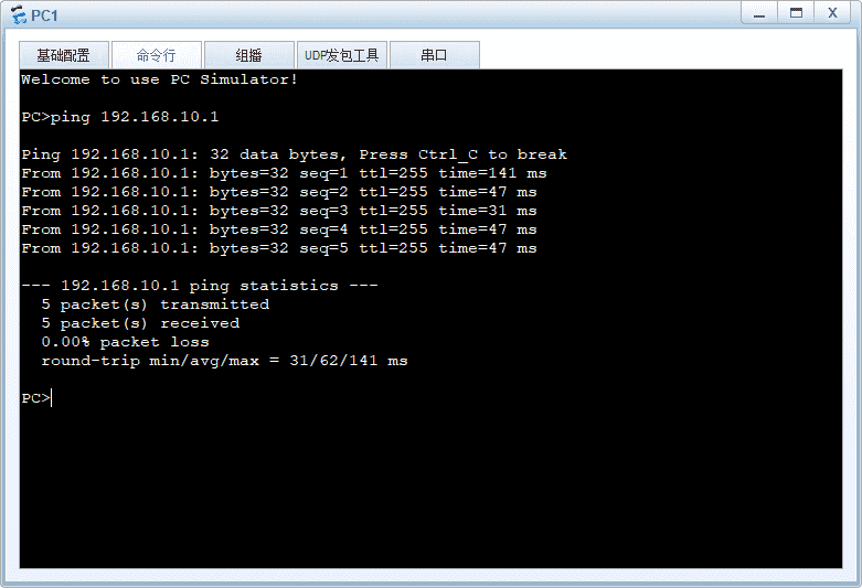
With this setup, PC1 belongs to the 192.168.10.0/24 network and uses 192.168.10.254 as its gateway. PC2 belongs to 192.168.20.0/24 and uses 192.168.20.254. Traffic between the two subnets is routed through AR1.
Option 2: VLANIF on a Layer 3 Switch
A Layer 3 switch can provide the VLAN gateways directly through VLANIF interfaces, eliminating the need for a separate router and subinterfaces. This design is commonly used in enterprise networks because routing is handled within the switch.
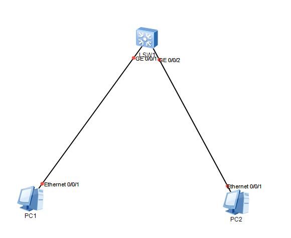
Create the VLANs on the CORE switch, place the two PC-facing ports in access mode, and assign each port to the appropriate VLAN. Then create one VLANIF interface per VLAN and configure the gateway address for each subnet.
<Huawei>system-view
[Huawei]sysname CORE

# 1. 创建VLAN
[CORE]vlan batch 10 20

# 2. 接入PC端口配置Access模式
# G0/0/1接PC1
[CORE]interface GigabitEthernet 0/0/1
[CORE-GigabitEthernet0/0/1]port link-type access
[CORE-GigabitEthernet0/0/1]port default vlan 10
[CORE-GigabitEthernet0/0/1]quit

# G0/0/2接PC2
[CORE]interface GigabitEthernet 0/0/2
[CORE-GigabitEthernet0/0/2]port link-type access
[CORE-GigabitEthernet0/0/2]port default vlan 20
[CORE-GigabitEthernet0/0/2]quit

# 3. 创建VLANIF三层接口(核心,不同网段网关)
[CORE]interface Vlanif 10
[CORE-Vlanif10]ip address 192.168.10.254 24
[CORE-Vlanif10]quit

[CORE]interface Vlanif 20
[CORE-Vlanif20]ip address 192.168.20.254 24
[CORE-Vlanif20]quit
Here, VLANIF 10 serves as the gateway for VLAN 10, while VLANIF 20 serves as the gateway for VLAN 20. Once the PCs use the corresponding gateway addresses, the Layer 3 switch can route traffic between the two VLANs without an external router.
The router-on-a-stick method is straightforward and economical for learning and small-scale labs. The VLANIF method requires a Layer 3 switch, but it is usually the more practical choice when the switching device can perform inter-VLAN routing directly.